Views: 0 Author: Site Editor Publish Time: 2026-08-06 Origin: Site
A top drive rarely arrives at the workshop with one neat, isolated fault.
The rig may report oil leakage, unstable hydraulic movement, abnormal motor noise or repeated alarms. Once the unit is opened, the real picture can be wider: failed seals, water or drilling-fluid contamination, corroded load-path components, worn bearing seats, damaged cables, or clearances that no longer meet the required limits.
That is why a NOV TDS-11SA top drive overhaul should not be treated as a larger version of a routine repair. The work is a controlled sequence of disassembly, cleaning, inspection, measurement, repair, replacement, reassembly and commissioning. Each stage supplies information for the next one.
This article explains that sequence from a workshop point of view. It draws on documented TDS-11SA overhaul work completed by JJC TEC, while recognizing that the final scope must always follow the condition, configuration, approved procedure and service requirements of the individual unit.
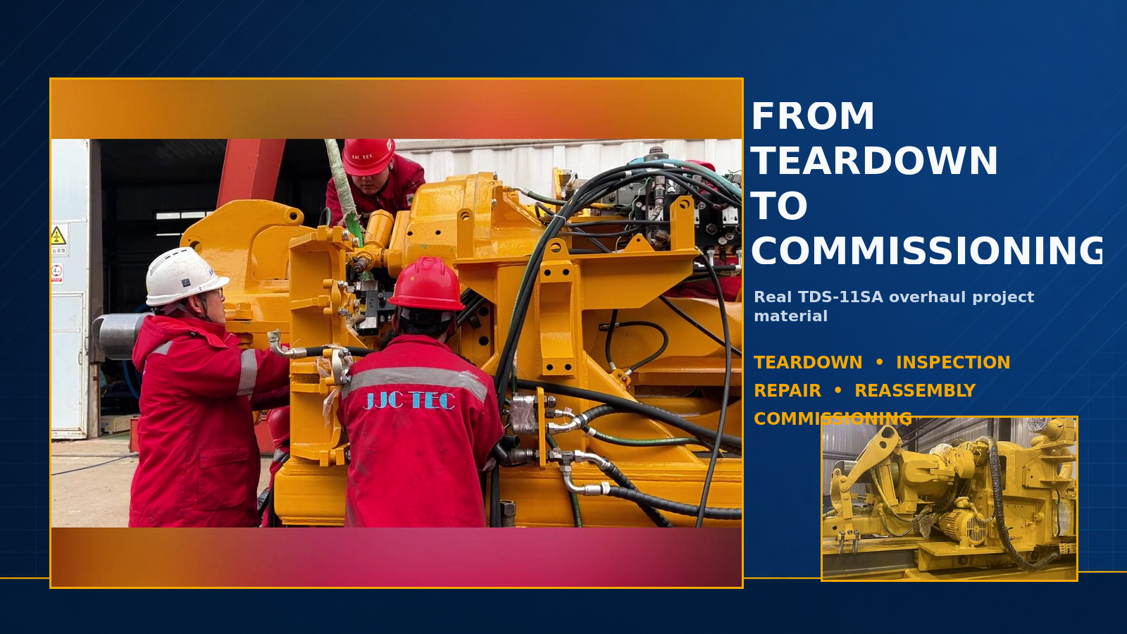
Good overhaul work begins with the operating history, not the toolbox.
Before disassembly, the repair team should confirm the equipment model, serial number, installed configuration and known modifications. The reported symptoms also need context. A leakage complaint means little without its location, operating pressure, frequency and recent maintenance history. The same is true for vibration, heat, noise and electrical alarms.
Useful pre-overhaul information includes:
equipment nameplate and serial number;
operating hours, if available;
recent fault and alarm records;
maintenance and parts-replacement history;
photos or video of the reported problem;
condition of the hydraulic oil and gear oil;
required completion date and rig schedule;
any requested inspection or documentation package.
This review helps establish the initial work scope. It also shows which parts should be prepared before teardown and which purchasing decisions must wait for measurement results.
No two units follow exactly the same repair list, but a controlled TDS-11SA overhaul normally moves through the following stages.
The unit should be photographed before cleaning or disassembly. Oil stains, missing covers, damaged connectors, loose hardware and previous field repairs can all provide useful evidence. Interfaces should be identified and protected, and oil samples or drainage condition should be recorded when this forms part of the agreed scope.
The incoming inspection is also the right time to compare the physical unit with the parts book and earlier records. A model designation alone does not confirm every installed component or revision.
Disassembly is not simply about removing parts quickly. Components, cables, hoses and fasteners must remain traceable. Open hydraulic ports should be capped, reusable parts should be protected from corrosion, and assemblies should be marked for inspection or replacement.
Depending on the work scope, the sequence may include the pipe handler and tilt assemblies, lifting components, hydraulic manifolds and cylinders, rotary head, oil tank, cooling system, main motors, gearbox, compound gears, bearings and spindle.
The order matters. It allows the workshop to preserve evidence and prevents contamination or handling damage from creating new problems during the overhaul.
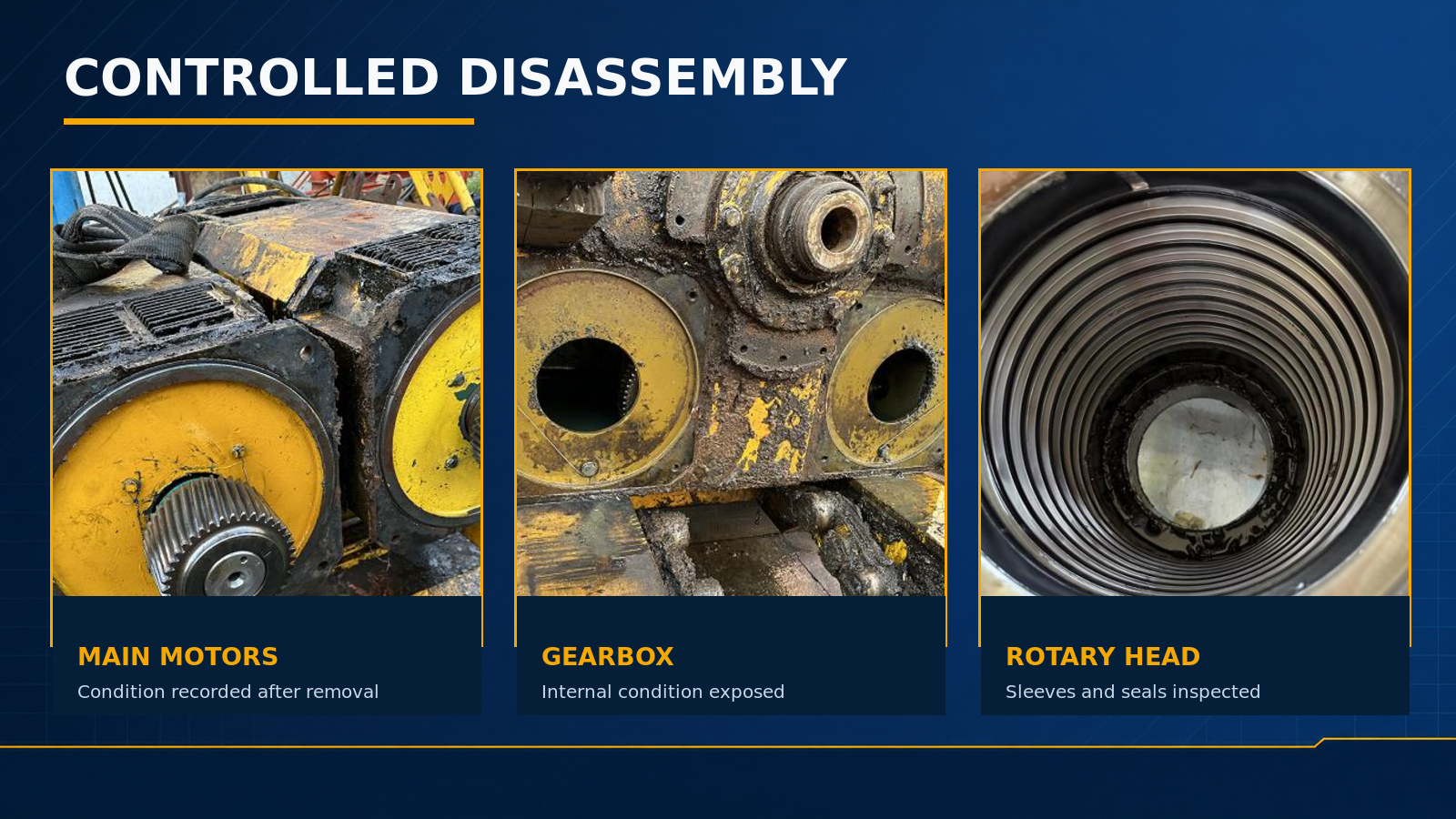
Once cleaned, the unit is reviewed as several connected systems rather than one machine.
The review may include insulation condition, phase resistance, bearings, oil-seal positions, shafts, heaters, temperature switches, fan motors, air passages and cooling components. A motor that can still rotate may nevertheless have internal rubbing, deteriorated insulation coating, bearing wear or a damaged seal seat.
Electrical readings should be assessed together with the physical condition. Replacing a bearing or seal without checking the related shaft surface can leave the cause of the failure in place.
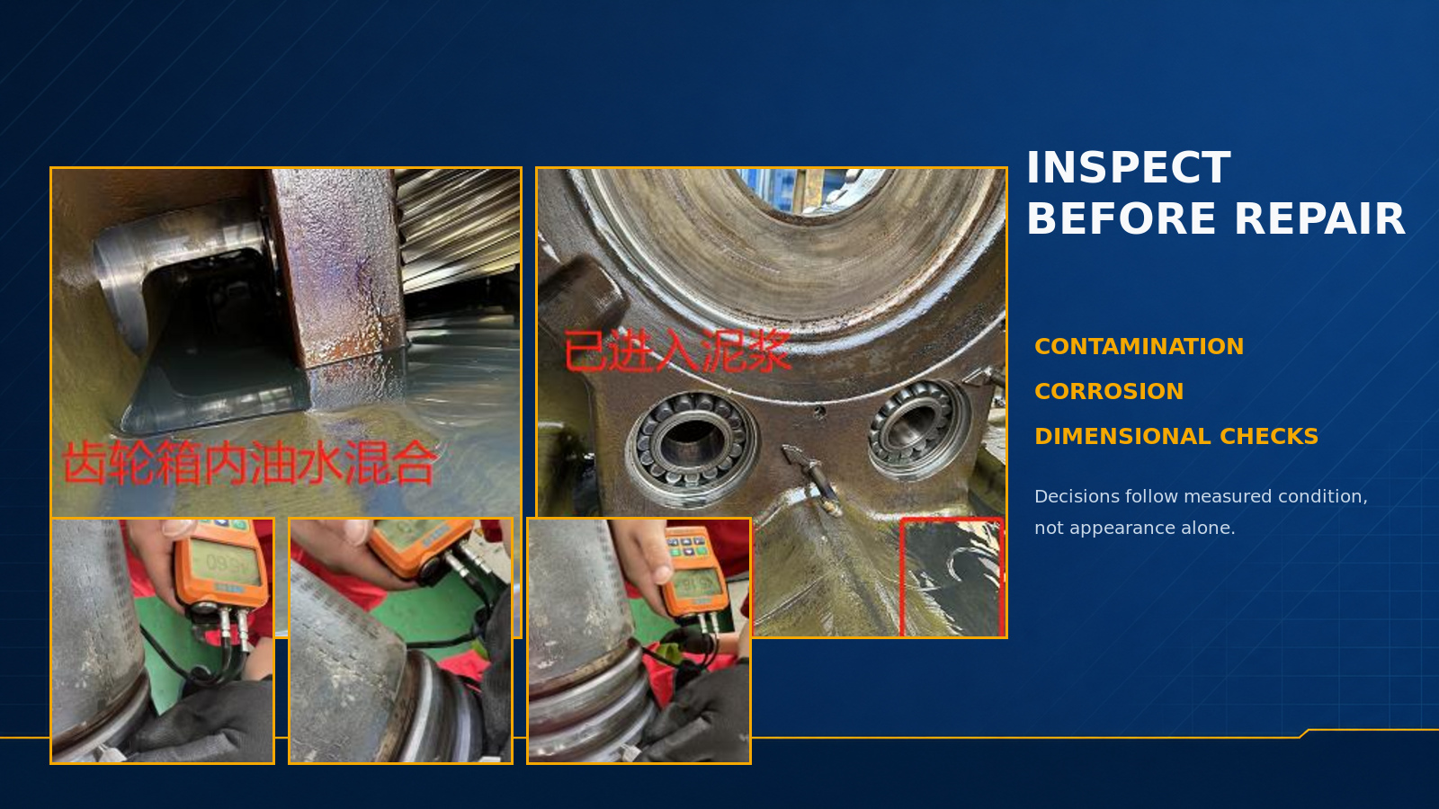
The gearbox inspection should look beyond visible gear teeth. Oil condition, internal contamination, corrosion, bearing fits, gear contact, shaft surfaces, sealing areas and load-path dimensions all matter.
In one documented TDS-11SA overhaul, the gearbox contained an oil-water mixture with a small amount of mud after a seal failure. Corrosion was found on the compound gears, load bearings, spindle gear disc and gearbox interior. The spindle was then checked at several positions with dimensional and ultrasonic measurements. A localized area was below the applicable acceptance requirement, so replacement—not cosmetic repair—was the appropriate decision.
That example is important because it shows why teardown findings must control the final parts list. Appearance alone cannot confirm whether a load-bearing component remains suitable for service.
The rotary head, valve manifolds, pumps, accumulators, filters, cylinders, hoses, hard lines and fittings should be inspected as one working circuit. Leakage at one seal may be linked to a damaged surface, worn joint, contamination or incorrect pressure setting elsewhere.
Oil passages must be cleaned before reassembly. Seals and O-rings should be selected for the actual component configuration, and replaced parts should be checked against the removed item rather than identified by appearance alone.
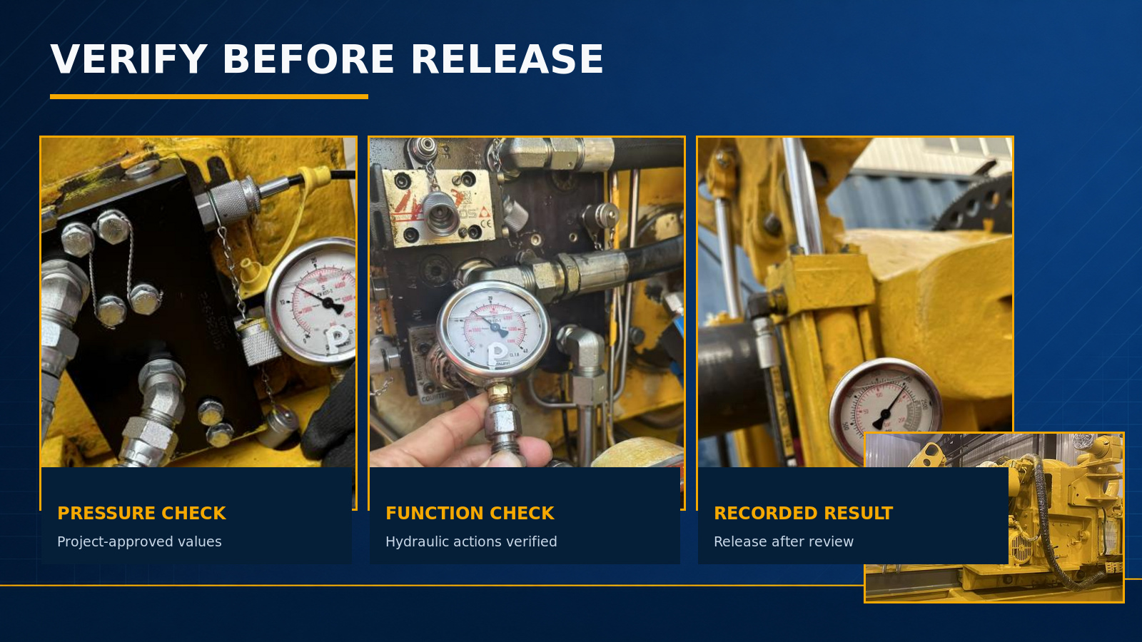
Pressure testing is performed where required by the approved overhaul procedure. The test pressure, holding time and acceptance criteria should be recorded for the specific component; values from another job should not be copied into a new project without verification.
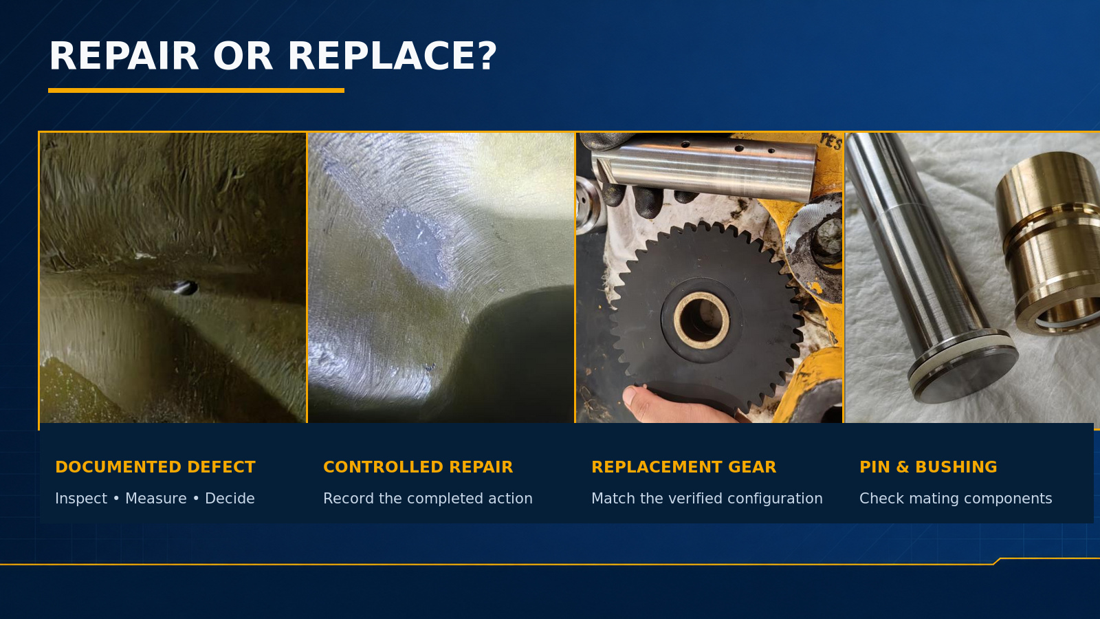
Back tong components, tilt cylinders, balance cylinders, pins, bushings, rollers, gooseneck, washpipe and IBOP-related parts are exposed to load, movement, pressure and a demanding operating environment. Their condition can affect both function and reassembly time.
Pin and bushing wear should be measured as a pair. Cylinder rods and seal locations need surface inspection before a seal kit is installed. Corroded or deformed fluid-path components should be assessed against the approved repair criteria rather than reused simply because they can be assembled.
An overhaul should not become an automatic replacement of every removed component. Nor should the workshop try to preserve a critical part after it has failed the applicable inspection criteria.
A practical decision normally considers:
measured dimensions and tolerances;
surface condition and corrosion depth;
bearing and seal fits;
electrical test results;
pressure or functional test results;
condition of mating components;
repair history and repeated failures;
lead time and project schedule;
approved manual, drawing and workshop procedure.
This produces three useful groups: parts approved for reuse, parts suitable for controlled repair, and parts that must be replaced. The inspection record should support the decision, particularly for major load-path, rotating, pressure-containing and electrical components.
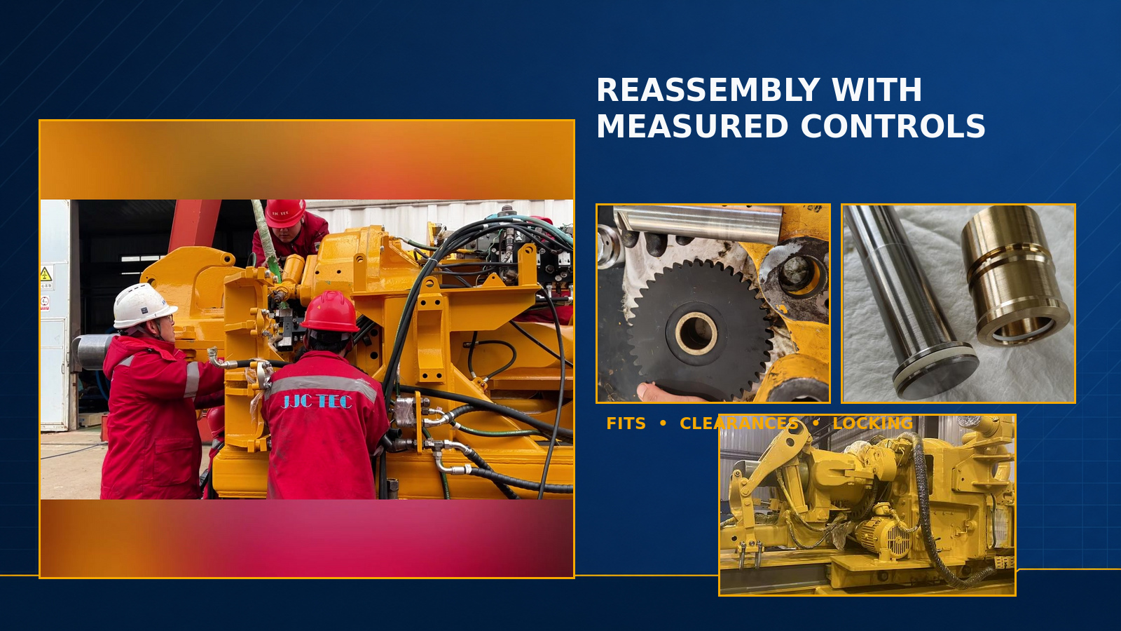
Cleanliness and traceability become even more important during reassembly. Internal passages, mounting faces and threaded holes must be clean. Bearings and sleeves should be installed with the correct method, and fasteners should be tightened and locked in accordance with the approved requirements.
Typical reassembly controls may include:
bearing and shaft-fit confirmation;
gearbox and spindle runout adjustment;
gear-mesh clearance measurement;
brake-disc and caliper checks;
spindle, gooseneck and connection alignment;
hydraulic-line cleanliness and routing;
cable insulation and continuity checks;
torque marking and lock-wire inspection;
replenishment of specified lubricants.
During the documented JJC TEC project, the workshop repeatedly adjusted the spindle assembly and checked runout, gear-mesh clearances, flatness and coaxiality before final commissioning. This is the kind of work that disappears once the guards are installed, but it has a direct effect on how the completed unit operates.
The first power-on test is not the beginning of commissioning. Checks should start before energization, with visual inspection, oil filling, cable verification, valve-coil checks, pressure-gauge installation and confirmation that observation points are ready.
A staged commissioning plan may include:
checking oil levels, lubrication points and leakage;
confirming cable resistance, insulation and grounding;
setting and recording hydraulic operating pressures;
testing lock pins, back tong, tilt and balance functions;
checking brake release and engagement;
running fan motors and checking airflow-related controls;
performing controlled spindle forward/reverse rotation;
checking abnormal sound, vibration, heat and leakage;
measuring final runout, flatness or coaxiality where required;
completing joint mechanical and electrical review before release.
The exact test program depends on the workshop setup, approved procedure and available interfaces. If a full-load or rig-integrated test cannot be performed in the workshop, that limitation should be stated clearly in the completion records.
A freshly painted top drive is easy to photograph. The more useful question is what happened before the paint was applied.
An overhaul record should make the technical path visible. Depending on the project, the handover package may include:
incoming-condition photographs;
disassembly and defect records;
dimensional inspection results;
electrical and insulation test records;
pressure or functional test records where applicable;
list of repaired, replaced and reused components;
assembly and commissioning records;
photographs before packing and shipment;
agreed recommendations for installation or follow-up checks.
These records help the customer review the completed scope and prepare the rig team for installation. They also create a useful baseline for future maintenance.
Some parts can be planned in advance: service consumables, known damaged items and components already included in the approved scope. Others should not be ordered until cleaning and inspection reveal their actual condition.
For example, a reported gearbox leak may lead to a seal order before teardown. After opening the unit, the workshop may also find water ingress, corrosion, damaged bearing surfaces or out-of-tolerance spindle dimensions. The second purchasing decision is therefore driven by inspection evidence, not by the original symptom.
The most workable approach is a two-stage parts plan:
Pre-teardown order: confirmed consumables, known failures and long-lead items that can be identified accurately.
Post-inspection order: bearings, gears, shafts, bushings, electrical components and other condition-based items released after measurement and technical review.
This reduces unnecessary purchasing without leaving the workshop unprepared for predictable needs.
If you are preparing a TDS-11SA or another NOV TDS unit for overhaul, the first technical discussion is more productive when it includes:
full equipment model and serial number;
clear nameplate photographs;
current location and planned workshop location;
operating hours and maintenance history, if available;
fault description, alarm history and leakage points;
photos and video of the current condition;
available parts book, drawings and previous repair records;
expected service scope;
required tests, documentation and delivery date.
Do not wait for a perfect parts list before starting the discussion. A clear description of the equipment and its condition is often more useful than an unverified list of part numbers.
There is no reliable standard duration for every unit. The schedule depends on the incoming condition, inspection findings, parts availability, repair scope, external processing and required testing. A preliminary schedule can be prepared before teardown, but it should be updated after inspection.
The known scope and planned-replacement items can be quoted in advance. Major condition-based work may require a provisional allowance or a second quotation after cleaning, measurement and inspection.
Replacement decisions should follow the approved overhaul procedure, component condition and inspection results. Service kits may be planned in advance, while major bearings and mating surfaces often require measurement and technical review.
A repair normally addresses a defined fault or component. An overhaul involves broader disassembly and inspection, followed by condition-based repair, replacement, controlled reassembly and commissioning of multiple connected systems.
Potential upgrades can be evaluated while the unit is dismantled, but they require a separate engineering review. Equipment configuration, motor and drive compatibility, controls, interfaces, structure and operating requirements must be checked before an upgrade scope is approved.
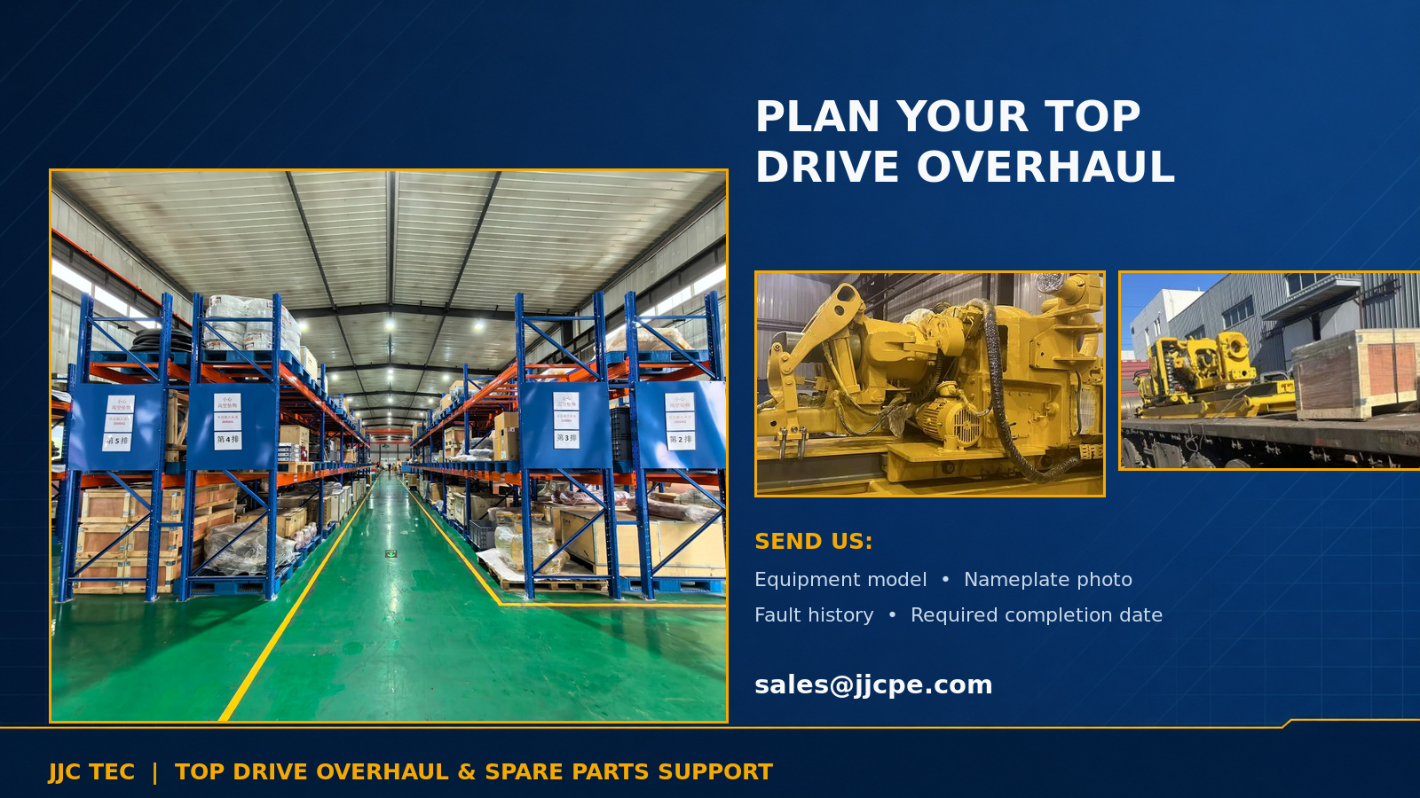
Preparing an overhaul for a NOV TDS top drive? Send JJC TEC the equipment model, serial number, nameplate photo, fault description, available maintenance records and expected delivery date. Our team can review the initial information, help define the inspection scope and organize the related repair and spare-parts requirements.
Contact JJC TEC or email sales@jjcpe.com.
For related spare-parts support, visit our One-Stop Spare Parts Service.
JJC TEC is an independent provider of drilling-equipment parts and services and is not affiliated with the named original equipment manufacturer. OEM names and trademarks are used for equipment identification only.


